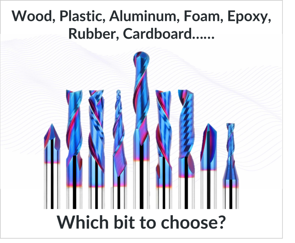
CNC Cutting Tool Geometry for Materials Starts with Understanding the Material
CNC cutting tool geometry for materials is where theory finally turns into real-world results. From the very first cut, the material you are machining determines whether your tool slices cleanly, burns, melts, or chatters. Wood, plastic, aluminum, and foam all behave differently under a cutting edge, and choosing the wrong geometry almost guarantees frustration.
Once you understand CNC cutting tool geometry for materials, tool selection stops feeling like guesswork. You begin by intentionally choosing bits based on how each material reacts to cutting forces, heat, and chip evacuation, rather than copying settings from a chart.
This is where Part 1, “A Beginner’s Guide to Mastering CNC Cutting Tool Geometry – Part 1” comes alive.
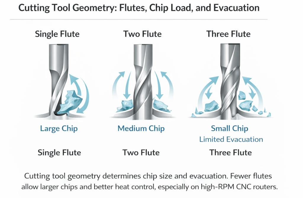
In Part 1, we broke down flutes, cutting direction, and helix angles. In this part, we apply those ideas directly to real materials you actually cut.
CNC Cutting Tool Geometry for Wood (Hardwood, Softwood, and Plywood)
Wood looks simple, but it is one of the most demanding materials when it comes to CNC cutting tool geometry for materials. Grain direction, density changes, internal stress, and moisture all influence how fibers behave under a cutting edge.
Upcut bits are often the first choice for wood because they evacuate chips aggressively. That chip evacuation keeps heat low and allows deeper cuts, especially in pockets. The tradeoff is top-edge tear-out, which happens because the cutting edge pulls fibers upward before slicing them.
Downcut bits solve that problem by pushing fibers downward into the material. This produces crisp, clean top edges that are ideal for signs, inlays, and visible surfaces. However, because chips are forced downward, heat builds quickly in deeper cuts unless dust collection and feed rates are managed carefully.
Compression bits combine both geometries and are designed specifically for sheet goods. When the cut is deep enough to engage both the upcut section at the bottom and the downcut section at the top, compression bits produce clean top and bottom edges at the same time. When they are run too shallow, they lose their advantage and behave like a single-geometry tool.
Most wood-related CNC problems—burn marks, fuzzy edges, tear-out—come down to CNC cutting tool geometry for materials not matching the type of cut being performed.
CNC Cutting Tool Geometry for Plastics (Acrylic, PVC, HDPE)
Plastics behave very differently from wood. They do not tear; they melt. That makes CNC cutting tool geometry for materials especially important when machining plastics.
Single-flute upcut tools and O-flute bits are commonly used for plastics because they provide maximum chip clearance. Wide flute spaces allow long, stringy plastic chips to escape before they re-melt and fuse back onto the tool. Polished cutting edges reduce friction and heat, which is critical for clean plastic cuts.
Multi-flute tools are one of the most common mistakes beginners make with plastics. Too many flutes reduce chip space, trap heat, and quickly lead to melting, edge smearing, or welded chips. When plastic melts, no amount of feed or speed adjustment can compensate for incorrect geometry.
With plastics, CNC cutting tool geometry for materials is less about cutting force and more about heat management. Geometry that slices cleanly and clears chips will outperform almost any numeric adjustment.
CNC Cutting Tool Geometry for Aluminum and Soft Metals
Aluminum introduces a new challenge: it is soft, but it is sticky. CNC cutting tool geometry for materials must prevent aluminum from welding itself to the cutting edge.
Single-flute carbide tools are popular for aluminum because they maximize chip evacuation and reduce heat. Lower helix angles are often preferred because they reduce chatter and limit upward pulling forces that can cause vibration. Aggressive rake angles help slice aluminum cleanly instead of rubbing it.
Using woodworking bits on aluminum almost always ends poorly. The geometry is wrong, heat builds quickly, chips weld, and tools fail. Aluminum demands geometry designed specifically for metal cutting, even on hobby or desktop CNC machines.
When aluminum cuts cleanly, the sound is steady, chips are well-formed, and the finish is bright. When geometry is wrong, the cut becomes noisy, rough, and unpredictable.
CNC Cutting Tool Geometry for Foam and Composite Materials
Foam may look forgiving, but CNC cutting tool geometry for materials matters here too. Foam tears easily when cutting forces are uneven or feeds are too slow.
Straight flute tools are commonly used for foam because they reduce lifting forces and keep the cut stable. Downcut geometry can help when foam has a surface skin that needs to stay intact. Ball nose tools are ideal for sculpted or 3D foam work because they produce smooth transitions.
Foam prefers faster feed rates with clean slicing action. Slow cutting tends to tear rather than cut, leaving ragged edges and inconsistent surfaces.
Why CNC Cutting Tool Geometry for Materials Matters More Than Settings
Every material has its own personality. Wood wants slicing. Plastic wants cooling. Aluminum wants chip evacuation. Foam wants speed and consistency.
When CNC cutting tool geometry for materials is chosen correctly, feeds and speeds become easier to dial in, surface finish improves, tool life increases, and the machine runs more smoothly. When geometry is wrong, no chart or calculator can save the cut.
Summary
CNC cutting tool geometry for materials is the bridge between theory and performance. Once you understand how geometry interacts with wood, plastics, metals, and foam, CNC machining becomes predictable instead of frustrating.
In Part 3, we pull everything together and show how tool geometry directly controls chip load, depth of cut, sound, deflection, and ultimately CNC feeds and speeds.
References
Harvey Tool Company. (n.d.). Chip load: What it is and why it matters.
https://www.harveyperformance.com/in-the-loupe/speeds-and-feeds-101/
CNC Cookbook. (n.d.). Feeds and Speeds [The Ultimate Guide, Updated for 2024]
https://www.cnccookbook.com/feeds-speeds/