Keywords: CNC cutting tool geometry, CNC router bits, upcut vs downcut, compression bits, CNC feeds and speeds, chip load for CNC, best CNC bits for wood, CNC tooling guide, CNC beginner tips, how to prevent tear-out CNC, CNC surface finish tips
Part 1 – Why Cutting Tool Geometry Matters More Than You Think (CNC Tool Geometry Basics)
Cut Smarter, Cut Cleaner: A Beginner’s Guide to CNC Cutting Tool Geometry
If you’ve spent any time around CNC machines, you already know the pattern. And before we go any further, this is where CNC cutting tool geometry quietly steps into the story: you unbox your machine, level it, square it up, fire up the spindle, load a beautiful piece of hardwood… and the moment that first carve is done, something just looks off.
The edges are fuzzy. The top surface has these jagged little torn fibers. Maybe you even see scorch marks where the bit burned the wood. Sometimes the whole thing sounds rough and angry, and in the worst cases, snap, a bit breaks.
Most beginners look at all that and think, “Maybe my machine isn’t rigid enough,” or “Maybe my settings were wrong.”
But here’s the truth: most people don’t learn until they’ve ruined a few boards:
Your CNC is only as good as the geometry of the tool you put in the spindle.
Tool geometry affects everything-heat. In fact, CNC cutting tool geometry is the foundation of why your cuts succeed or fail. It influences, chip flow, finish quality, accuracy, cut time, and even how long your bits last.
So before we talk about feeds, speeds, or fancy cutting strategies, let’s slow down and really understand the parts of a cutting tool and how they behave.
CNC Feeds and Speeds Calculator
What Tear-Out, Burn Marks, and Rough Edges Actually Are
Understanding these problems makes everything else make sense.
❖ Tear-Out
Tear-out happens when the bit rips wood fibers instead of slicing them. The result looks like splintering, fraying, or chipping along the grain or at edges.
Why it happens:
- Wrong cutting edge direction
- Dull tool
- Too many flutes
- Incorrect feed rate
- Wrong tool for the material
❖ Burn Marks
Burning shows up as dark streaks on the wood. It means heat isn’t leaving the cut. That’s almost always due to:
- Tool rubbing instead of cutting
- Too slow a feed rate
- Too many flutes (chips can’t escape)
- Wrong geometry (like using a downcut where heat builds up)
❖ Rough Edges
Sometimes the cut looks shredded or uneven. That usually means:
- Incorrect flute direction
- Poor chip evacuation
- Wrong helix angle
- Geometry not matched to material
All of these issues stem from the same root cause: tool geometry determines how the tool interacts with the material.
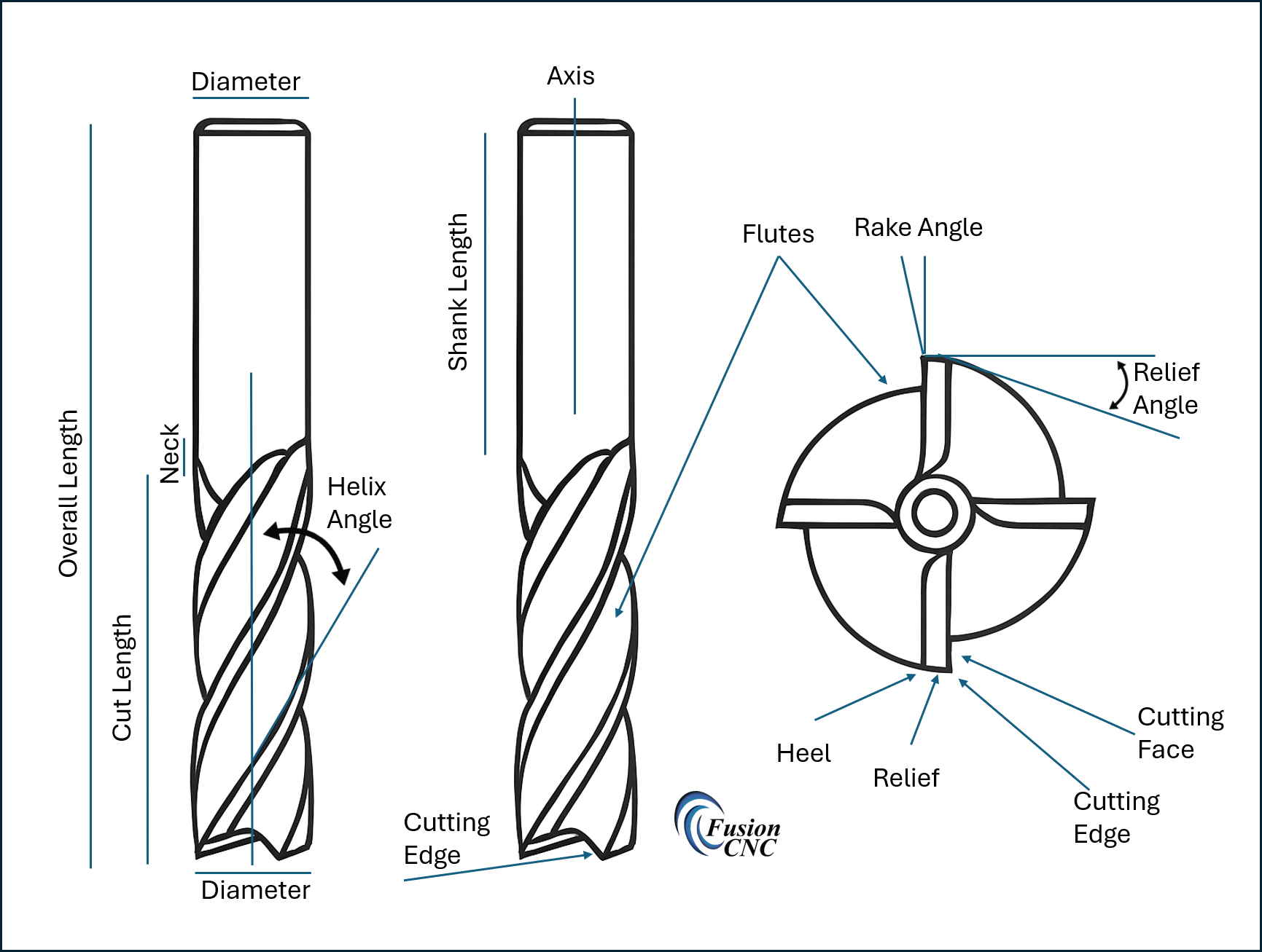
Breaking Down CNC Cutting Tool Geometry (Key Concepts Beginners Need to Know)
1. Flutes – The Highways for Your Chips (Core of CNC Cutting Tool Geometry)
Flutes are the grooves along the bit. Their job is to carry chips out of the cut.
More flutes = less room for chips. Fewer flutes = more airflow and chip evacuation.
For wood: 1–2 flutes (because wood makes big chips).
For plastics: 1 flute (because plastics melt easily).
For aluminum: 1–3 flutes (because aluminum needs sharp, polished chips).
If chips have nowhere to go, the bit rubs and overheats, leaving burn marks, melted plastic, or welded aluminum chips.
2. Cutting Edge Geometry – Upcut, Downcut, and Compression
This is where everything starts to click.
Upcut – The cutting edge, starting at the tip, touches the wood first when moving along the surface of the material and goes up at an angle away from the direction of travel. So, looking at it with the tip down the flute seems like it is going from the bottom twisting up toward the right, so as it is cutting, the spindle is rotating in a clockwise direction, the chips follow the flute in an upward direction.
- Pulls chips up toward the spindle
- Creates clean bottom surfaces
- Can tear out the top of the wood
Think of it as a little tornado pulling fibers upward.
Downcut – The cutting edge behaves almost like the mirror opposite of an upcut bit, but with its own quirks and advantages. Instead of the flute lifting chips upward (as explained in the Upcut section), a downcut bit forces the cutting motion downward into the material. So if you’re looking at the bit with the tip down, the flute spirals down toward the left, meaning that as the spindle rotates clockwise, the cutting edge is pushing fibers and chips down toward the table surface.
- Pushes fibers down into the material rather than lifting them up
- Creates clean, crisp top surfaces because the downward cutting motion shears the fibers before they can lift or tear
- Tends to trap chips in the cut because the tool is forcing everything downward instead of pulling chips up and out
Think of a downcut bit as the tool you reach for when you want your top surface to look perfect straight off the machine-no frayed edges, no fuzzing, no splintering.
But there’s a trade‐off: because the downcut pushes chips downward, they have nowhere to go in deep cuts. That trapped chip load quickly generates heat, causing burning, scorching, and sometimes even tool failure.
So while a downcut excels at keeping the top edge crisp, it struggles in deep pockets without proper chip evacuation.
Perfect for clean edges, terrible for deep pockets.
Compression (Upcut + Downcut Combined) – A bit that combines the behavior of both upcut and downcut geometry in one tool, creating a unique cutting action that pulls fibers down from the top and up from the bottom at the same time. This dual‑direction cutting motion is designed specifically to eliminate tear‑out on both the top and bottom surfaces of sheet goods like plywood, MDF, laminates, and veneered materials. Instead of choosing between clean tops (downcut) or clean bottoms (upcut), a compression bit gives you both, as long as you cut deep enough to engage both parts of the geometry.
A compression bit has downcut geometry on the top of the bit and upcut geometry at the bottom.
Result:
- Clean top and bottom edges
- Perfect for plywood and laminates
BUT: If you don’t cut deep enough to reach both geometries, it behaves like an upcut bit.
This is one of the most misunderstood tools in CNC.
3. Helix Angle – The Twist of the Bit
The helix angle controls how aggressively a bit pulls material out of the cut. In simple terms, the helix angle is the twist of the cutting edge as it wraps around the bit. A higher helix means the flute spirals upward more steeply, helping lift chips away faster and creating a smoother, slicing action. A lower helix means the flute has a gentler twist, which keeps the cutting force more horizontal and controlled rather than pulling upward. This twist affects chip evacuation, heat buildup, vibration, surface finish, and even how securely your workpiece must be clamped.
- High Helix (steeper twist)
- Smoother cuts
- Quieter
- Less vibration
- But: creates a strong upward force → can lift the workpiece if it’s not clamped well
- Low Helix (gentler twist)
- Stronger, more controlled cutting
- Better for hardwoods and metals
- Less pull on the material
If your CNC sounds like it’s chattering or vibrating, the helix angle is often the silent culprit.
Part 1 Summary
Understanding CNC cutting tool geometry is the first real turning point for CNC beginners.
Most CNC issues aren’t mechanical-they’re geometric.
When you understand tool geometry, you stop fighting your machine and start getting the clean, predictable results you expected.
What’s Coming in Part 2
Part 2 digs deeper into CNC cutting tool geometry and shows you how all of this comes together when you move from theory to real‑world cutting-wood, plastics, aluminum, and foam- each with its own personality, challenges, and tool geometry sweet spots. It’s where everything you’ve learned here starts to make sense in a practical, hands‑on way.
For the full Blog, click here
Bibliography
Amana Tool. (n.d.). CNC router bit selection guide. https://www.amanatool.com/articles
CNCCookbook. (n.d.). CNC router tooling basics. https://www.cnccookbook.com/cnc-router-tooling-basics/
Groover, M. P. (2010). Fundamentals of modern manufacturing: Materials, processes, and systems (5th ed.). Wiley.
Harvey Performance Company. (n.d.). Cutting tool technical resources. https://www.harveyperformance.com/resources/
Kalpakjian, S., & Schmid, S. R. (2013). Manufacturing engineering and technology (7th ed.). Pearson.
Kennametal. (n.d.). Engineering resources for machining. https://www.kennametal.com/us/en/resources/engineering-resources.html
Onsrud Cutter. (n.d.). Chip load recommendations. LMT Onsrud. https://www.onsrud.com/Eng/Support/ChipLoads
Smid, P. (2008). CNC programming handbook (3rd ed.). Industrial Press.
Vectric Ltd. (n.d.). Tool database documentation. https://docs.vectric.com
Whiteside Machine Company. (n.d.). Router bit information. https://whitesiderouterbits.com/pages/router-bit-info