Picture this: You’ve just unboxed your brand-new CNC machine. It’s beautiful, it’s precise, and you can’t wait to start making things. You load up your first piece of wood, fire up the spindle, and… the results are disappointing. The edges are rough, there’s tear out everywhere, and your expensive end mill looks like it went through a blender. Sound familiar?
Here’s the thing that nobody tells beginners: the cutting tool is everything. Your CNC machine might be capable of incredible precision, but if you don’t understand cutting tool geometry, you’re essentially trying to paint a masterpiece with a house brush. The good news? Once you understand the basics of how cutting tools work, everything else starts to make sense.
This guide will take you from “I have no idea what all these angles mean” to “I can select the perfect tool for any job.” We’ll break down every aspect of cutting tool geometry in plain English, with real-world examples that will make you a smarter, more successful CNC operator.
Chapter 1: The Anatomy of a Cutting Tool – Your New Best Friends
Before we dive into the technical stuff, let’s get familiar with the basic parts of a cutting tool. Think of this as meeting the cast of characters in your CNC story.
The Players in Your Cutting Tool Drama
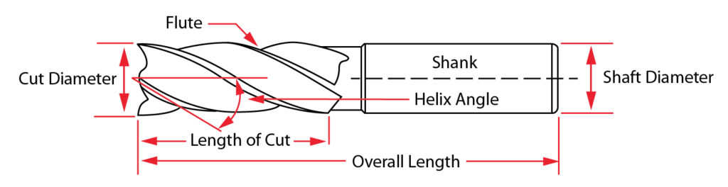
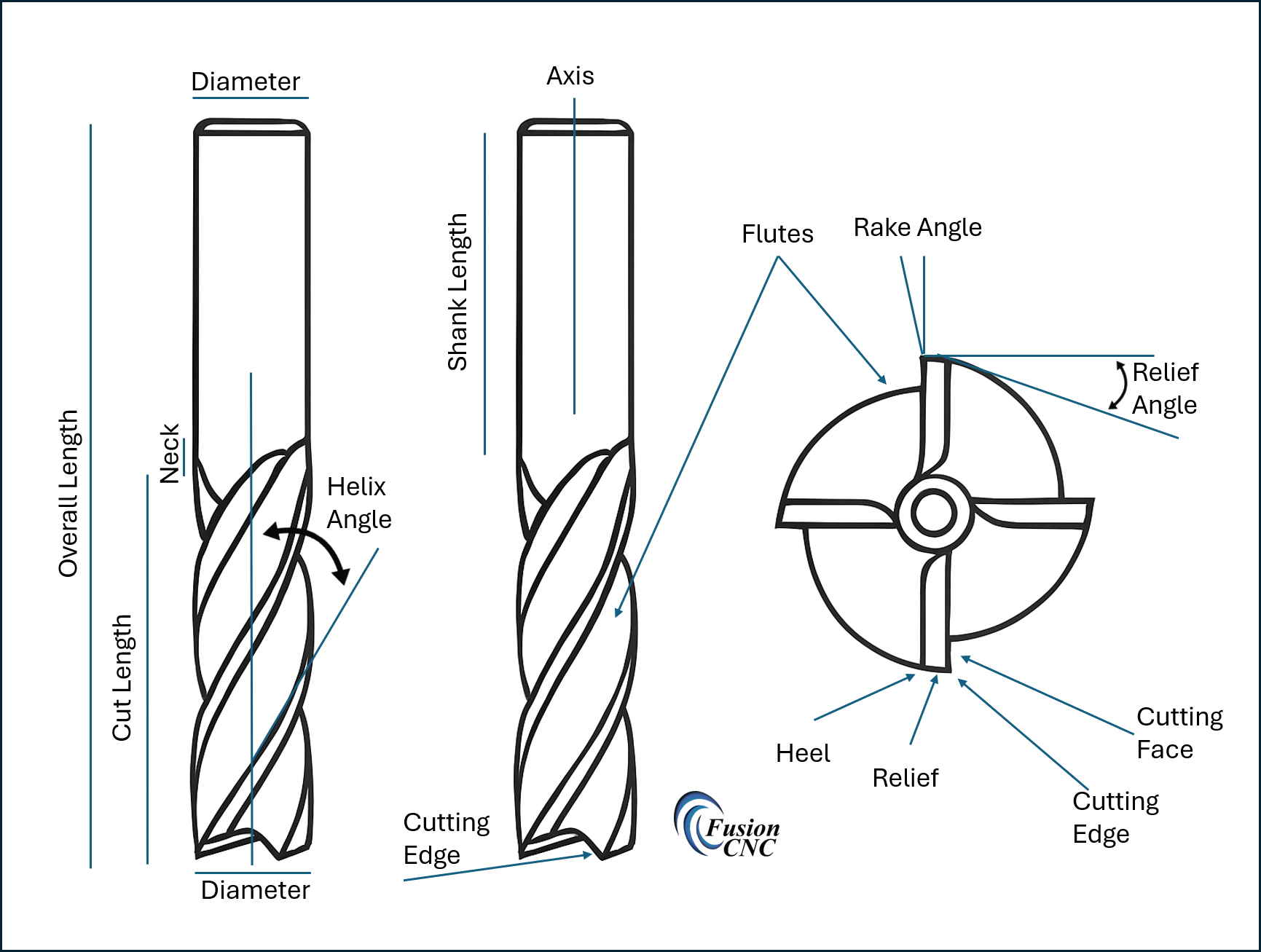
The Shank: This is the part that goes into your spindle. It needs to be perfectly round and smooth so your machine can grip it securely. A damaged shank will cause runout, which leads to poor surface finish and premature tool wear.
The Flutes: These are the spiral grooves that wrap around the tool. They serve two critical purposes: they form the cutting edges, and they provide channels for chip evacuation. More flutes generally mean better surface finish but slower material removal.
The Cutting Edge: This is where the magic happens. The cutting edge is formed where the flute meets the outer diameter of the tool. The geometry of this edge determines how well your tool cuts.
The Core: This is the solid center of the tool between the flutes. A larger core means a stronger tool, but fewer flutes. It’s always a balance.
The Point/Tip: For end mills, this is the bottom of the tool. The geometry here affects how well the tool can plunge into material and what kind of surface finish you’ll get on horizontal surfaces.
Why Geometry Matters: The Physics of Cutting
When your cutting tool engages with material, it’s not just “cutting” in the way you might think. What’s actually happening is a complex process of shearing, where the tool edge forces material to fail along a specific plane. The geometry of your tool determines how efficiently this happens.
Think of it like this: imagine trying to slice a tomato with a butter knife versus a sharp chef’s knife. Both will eventually cut through, but the sharp knife with the proper geometry will do it cleanly, with less force, and without crushing the tomato. Your CNC cutting tools work the same way.
Chapter 2: The Seven Sacred Angles – Decoding Tool Geometry
Now we’re getting to the meat of the matter. There are seven key geometric features that define how a cutting tool behaves. Don’t worry – we’ll break each one down so it makes perfect sense.
1. Helix Angle: The Spiral That Makes It Work
The helix angle is the angle at which the flutes spiral around the tool. Picture a barber pole – that’s a helix. This angle has a huge impact on how your tool performs.
Low Helix Angle (10-25 degrees):
•Best for: Hard materials, heavy cuts, maximum tool strength
•Characteristics: More aggressive cutting action, better for roughing
•Downside: Can cause more vibration, rougher surface finish
High Helix Angle (40-60 degrees):
•Best for: Soft materials, finishing passes, smooth cuts
•Characteristics: Shears material more efficiently, better surface finish
•Downside: Weaker tool, more prone to deflection
Why it matters: The helix angle affects how the chip is formed and evacuated. A steeper helix pulls the chip up and out of the cut more efficiently, but it also creates more axial force that tries to pull the tool into the material.
2. Rake Angle: The Cutting Edge’s Attack Angle
The rake angle is the angle between the cutting edge and a line perpendicular to the surface being cut. This is where things get really interesting because rake angle has a massive impact on cutting forces and tool life.
Positive Rake Angle:
•What it does: The cutting edge “leans forward” into the cut
•Benefits: Lower cutting forces, better surface finish, easier cutting
•Best for: Soft materials like aluminum, wood, plastics
•Downside: Weaker cutting edge, more prone to chipping
Negative Rake Angle:
•What it does: The cutting edge “leans back” away from the cut
•Benefits: Stronger cutting edge, better for interrupted cuts
•Best for: Hard materials, rough conditions, heavy cuts
•Downside: Higher cutting forces, more heat generation
Zero Rake Angle:
•What it does: The cutting edge is perpendicular to the surface
•Benefits: Good compromise between strength and cutting efficiency
•Best for: General-purpose applications
3. Relief Angle (Clearance Angle): Preventing the Rub
The relief angle is the angle that slopes away from the cutting edge on the back side of the tool. This might seem like a minor detail, but it’s absolutely critical.
Why you need it: Without relief angle, the back of the tool would rub against the workpiece, creating friction, heat, and poor surface finish. It’s like trying to cut with a chisel that’s completely flat on the back.
Typical values: Most cutting tools have relief angles between 5-15 degrees. More relief gives better clearance but weakens the cutting edge.
The Goldilocks principle: Too little relief causes rubbing and heat. Too much relief weakens the cutting edge and causes premature wear. You want it just right.
4. End Cutting Edge Angle: The Bottom Line
This is the angle of the cutting edge at the end of the tool (the bottom). It affects how well the tool can plunge into material and what kind of surface finish you get on horizontal surfaces.
Square End (90 degrees):
•Best for: General purpose work, good corner definition
•Characteristics: Strong cutting edge, good for most applications
Corner Radius:
•Best for: Better surface finish, stronger than sharp corners
•Characteristics: Distributes cutting forces over a larger area
•Downside: Can’t create sharp internal corners
Ball End:
•Best for: 3D contouring, smooth curves
•Characteristics: Can create smooth, curved surfaces
•Downside: Slower material removal, requires more complex programming
5. Side Cutting Edge Angle: The Profile Maker
This is the angle of the cutting edges along the side of the tool. It affects chip formation and the strength of the cutting edge.
Straight (0 degrees):
•Characteristics: Maximum tool strength, good for heavy cuts
•Best for: Roughing operations, maximum material removal
Angled (typically 30-45 degrees):
•Characteristics: More gradual engagement, better surface finish
•Best for: Finishing operations, reducing vibration
6. Core Diameter: The Strength Factor
The core diameter refers to the diameter of the solid center of the tool, measured between the flutes. This directly affects the strength and rigidity of the tool.
Larger Core:
•Benefits: Stronger tool, less deflection, can handle heavier cuts
•Downside: Fewer flutes, less efficient chip evacuation
Smaller Core:
•Benefits: More room for flutes, better chip evacuation
•Downside: Weaker tool, more prone to breakage
7. Number of Flutes: The Balancing Act
The number of flutes affects surface finish, material removal rate, and chip evacuation.
2 Flutes:
•Best for: Roughing, soft materials, maximum chip evacuation
•Characteristics: Fast material removal, good for deep cuts
•Surface finish: Rougher, but acceptable for many applications
3 Flutes:
•Best for: General purpose, good balance of speed and finish
•Characteristics: Good compromise between material removal and surface finish
4+ Flutes:
•Best for: Finishing, hard materials, best surface finish
•Characteristics: Slower material removal but excellent surface quality
•Limitation: Can clog with chips in soft materials
Chapter 3: How Geometry Affects Real-World Performance
Now that you understand the individual elements, let’s talk about how they work together to affect your machining results.
Surface Finish: The Visual Quality Test
Surface finish is often the first thing people notice about a machined part. Several geometric factors affect surface finish:
Tool sharpness: This seems obvious, but a dull tool will always produce a poor surface finish, regardless of other factors.
Number of flutes: More flutes generally mean better surface finish because each flute removes a smaller chip.
Helix angle: Higher helix angles typically produce better surface finishes by shearing the material more efficiently.
Feed per tooth: This is determined by your programming, but the tool geometry affects what feed rates are practical.
Tool Life: Making Your Investment Last
Tool life is affected by how the cutting forces are distributed and how efficiently heat is removed from the cutting zone.
Rake angle: Positive rake angles reduce cutting forces but create weaker cutting edges. It’s a trade-off.
Relief angle: Proper relief prevents rubbing and reduces heat buildup.
Core diameter: Larger cores resist deflection and last longer under heavy cutting conditions.
Coating: While not strictly geometry, tool coatings work with geometry to extend tool life.
Cutting Forces: The Physics of Material Removal
Understanding cutting forces helps you select appropriate cutting parameters and avoid tool breakage.
Factors that increase cutting forces:
•Negative rake angles
•Dull tools
•Excessive feed rates
•Hard materials
•Deep cuts
Factors that decrease cutting forces:
•Positive rake angles
•Sharp tools
•Appropriate speeds and feeds
•Proper tool geometry for the material
Chapter 4: Selecting the Right Tool for Your Material
Different materials require different tool geometries. Here’s your guide to making the right choices.
Wood and Wood Products
Wood is generally easy to machine, but it has unique characteristics that affect tool selection.
Grain direction: Wood has different properties parallel and perpendicular to the grain. This affects how chips are formed and how the tool should be oriented.
Moisture content: Wet wood machines differently than dry wood. Higher moisture content can cause chips to stick to the tool.
Species variations: Softwoods like pine machine differently than hardwoods like oak. Abrasive woods like teak require special consideration.
Recommended geometry for wood:
•High helix angle (45-60 degrees) for smooth cutting
•Positive rake angle for easy cutting
•Sharp cutting edges
•2-3 flutes for good chip evacuation
•Compression geometry for plywood to prevent tearout
Plastics: The Sticky Situation
Plastics can be tricky because they tend to melt and stick to cutting tools.
Thermoplastics: These soften when heated, so heat management is critical.
Thermosets: These don’t melt but can be abrasive.
Recommended geometry for plastics:
•Very sharp cutting edges
•Positive rake angles to reduce heat
•Polished flutes to prevent sticking
•Adequate relief angles
•Consider single-flute tools for maximum chip evacuation
Foam: The Gentle Giant
Foam is extremely easy to cut but requires specific tool geometry to avoid tearing.
Challenges with foam:
•Very low cutting forces can cause deflection
•Material can tear rather than cut cleanly
•Chips can clog flutes
Recommended geometry for foam:
•Very sharp tools
•High helix angles
•Minimal relief angles (foam doesn’t create much friction)
•Consider hot knife cutting for some applications
Composites: The Modern Challenge
Composite materials like carbon fiber and fiberglass are increasingly common but challenging to machine.
Challenges with composites:
•Abrasive fibers wear tools quickly
•Delamination can occur
•Different layers may have different properties
Recommended geometry for composites:
•Diamond-coated tools for abrasion resistance
•Sharp cutting edges to minimize delamination
•Appropriate speeds to avoid heat buildup
•Consider compression geometry for layered materials
Chapter 5: Common Problems and Their Geometric Solutions
Let’s troubleshoot some common issues you might encounter and how tool geometry can help solve them.
Problem: Excessive Tool Wear
Possible geometric causes:
•Insufficient relief angle causing rubbing
•Negative rake angle creating excessive cutting forces
•Wrong tool material for the application
Solutions:
•Increase relief angle (but not too much)
•Consider more positive rake angle
•Upgrade to coated or carbide tools
Problem: Poor Surface Finish
Possible geometric causes:
•Too few flutes for the application
•Dull cutting edges
•Inappropriate helix angle
Solutions:
•Use more flutes for finishing operations
•Ensure tools are sharp
•Match helix angle to material and operation
Problem: Tool Breakage
Possible geometric causes:
•Tool too small for the cutting forces
•Excessive deflection due to small core diameter
•Wrong geometry for the material
Solutions:
•Use larger, more rigid tools
•Reduce cutting forces with geometry changes
•Match tool geometry to material properties
Problem: Chip Clogging
Possible geometric causes:
•Too many flutes for the material
•Insufficient chip evacuation space
•Wrong helix angle for the application
Solutions:
•Use fewer flutes
•Consider roughing end mills with chip breaker geometry
•Adjust helix angle for better chip evacuation
Chapter 6: Advanced Concepts for Growing Machinists
Once you’ve mastered the basics, these advanced concepts will help you optimize your tool selection even further.
Variable Helix Tools
Some advanced tools use variable helix angles along the length of the tool. This helps reduce vibration and chatter by preventing harmonic resonance.
Unequal Spacing
Tools with unequally spaced flutes also help reduce vibration by breaking up harmonic patterns.
Specialized Geometries
Roughing end mills: Feature serrated cutting edges that break chips into smaller pieces for easier evacuation.
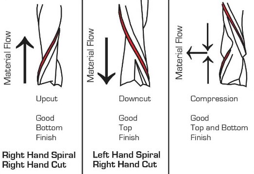
Compression tools: Have both up-cut and down-cut geometries to prevent tearout on both surfaces of sheet materials.
Tapered tools: Allow access to deep pockets while maintaining rigidity.
Chapter 7: Building Your Tool Library
As you grow in your CNC journey, you’ll want to build a comprehensive tool library. Here’s how to approach it strategically.
Essential Tools for Beginners
1/4″ 2-flute up-cut spiral: Your go-to tool for roughing in wood and soft materials.
1/8″ 2-flute up-cut spiral: For detail work and smaller features.
1/4″ compression bit: Essential for plywood and other sheet goods.
60-degree V-bit: For sign making and decorative work.
1/2″ surfacing bit: For flattening and surface preparation.
Intermediate Additions
Ball end mills: For 3D carving and contouring.
Tapered ball nose: For deep 3D work with good surface finish.
Specialty bits: Dovetail bits, keyhole bits, etc., for specific joinery.
Advanced Tools
Variable helix tools: For vibration-free cutting in challenging materials.
Coated tools: For extended life in abrasive materials.
Custom tools: For high-volume production of specific features.
Chapter 8: Maintenance and Care
Your cutting tools are precision instruments that require proper care to perform at their best.
Storage
Tool holders: Protect cutting edges from damage.
Organization: Know what tools you have and their condition.
Environment: Keep tools dry to prevent corrosion.
Inspection
Visual inspection: Look for chips, wear, and damage.
Runout checking: Ensure tools run true in your spindle.
Sharpness testing: Dull tools cause more problems than broken ones.
Sharpening and Reconditioning
When to sharpen: Before tools become completely dull.
Professional services: Often more cost-effective than buying new tools.
Coating renewal: Some coatings can be renewed during sharpening.
Conclusion: Your Journey Continues
Understanding cutting tool geometry is like learning a new language – at first, it seems overwhelming, but once you start to understand the basics, everything begins to make sense. The key is to start with the fundamentals and build your knowledge through experience.
Remember, every material is different, every machine has its own characteristics, and every project presents unique challenges. The principles in this guide will give you the foundation you need, but there’s no substitute for hands-on experience.
Start with simple projects using basic tools, and gradually expand your knowledge and tool library as you take on more complex work. Pay attention to how different geometries affect your results, and don’t be afraid to experiment.
Most importantly, remember that cutting tool geometry is just one piece of the CNC puzzle. Proper speeds and feeds, good workholding, and sound machining practices are equally important. But with a solid understanding of tool geometry, you’ll be well-equipped to tackle any project that comes your way.
Your CNC journey is just beginning, and understanding cutting tool geometry is one of the most important skills you can develop. Take your time, be patient with yourself, and enjoy the process of learning. Before you know it, you’ll be selecting tools like a pro and achieving results that would have seemed impossible when you started.
Welcome to the world of precision machining – your tools are ready, and now you understand how to use them!
References:
[1] Harvey Performance Company. “End Mill Geometry Guide.” Available at: https://www.harveyperformance.com/in-the-loupe/end-mill-geometry-guide/
[2] Sandvik Coromant. “Cutting Tool Geometry.” Available at: https://www.sandvik.coromant.com/en-us/knowledge/cutting-tool-geometry
[3] Kennametal. “Understanding Tool Geometry.” Available at: https://www.kennametal.com/us/en/resources/knowledge-center/understanding-tool-geometry.html
[4] CNC Cookbook. “End Mill Basics.” Available at: https://www.cnccookbook.com/end-mill-basics/